
Welcome to the store
Write a short welcome message here
Shop by Category

New In
-
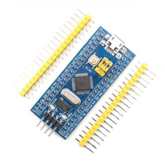 Bluepill ARM Cortex Board₹550.00
 -
 ARM Cortex M3 Development Board₹850.00
 -
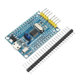 ARM Cortex M0 Development Board₹399.00
 -
 N76E003 Mini Development Board₹250.00
 -
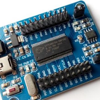 CY7C68013A Development board₹750.00
 -
Product on sale
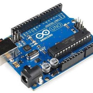 Arduino UNO R3 Board₹550.00
 -
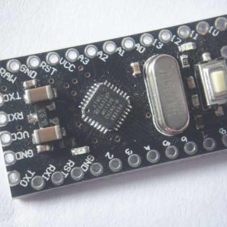 Arduino Pro Mini₹399.00
 -
Product on sale
 InVentor UNO – Arduino UNO Compatible Board₹425.00
 -
Product on sale
 Arduino Leonardo Board₹600.00
 -
 Arduino Pro Micro – 5V/16MHz₹650.00
 -
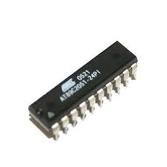
 AT89S52₹65.00
 -
 AT89C2051₹36.00
On Sale


Best Sellers
-
Bluepill ARM Cortex Board₹550.00
-
ARM Cortex M3 Development Board₹850.00
-
ARM Cortex M0 Development Board₹399.00
-
N76E003 Mini Development Board₹250.00
-
CY7C68013A Development board₹750.00
-
Product on saleArduino UNO R3 Board₹550.00
-
Arduino Pro Mini₹399.00
-
Product on saleInVentor UNO – Arduino UNO Compatible Board₹425.00
-
Product on saleArduino Leonardo Board₹600.00
-
Arduino Pro Micro – 5V/16MHz₹650.00
-
AT89S52₹65.00
-
AT89C2051₹36.00